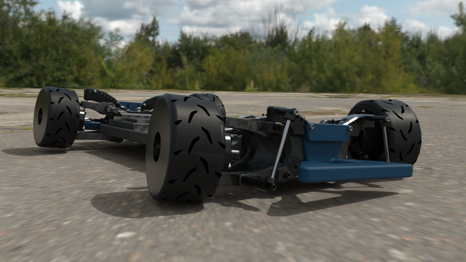
A custom 1/7 scale, four-motor RC car with one independent brushless hub motor at each wheel, plus ESP32 control, wheel-speed feedback, an inertial sensor, custom suspension, and dual bell-crank steering.
Rendered view of the chassis and four-motor layout.
4Independent hub motors
550KVMotor rating
50AESC at each wheel
1 HzDefault offline logging
01 / Project overview
System overview
Hubba Hubba is a custom hub-motor RC car with four independently driven wheels. The engineering project combines the mechanical, electrical, and embedded-control systems of a 1/7 scale RC car: each wheel uses a separate brushless hub motor and ESC, while an ESP32 processes radio inputs and sensor feedback to command the drivetrain and steering.
DrivetrainIndependent electric drive at all four wheels
ControlCustom motor, steering, drive-enable, and fallback logic
FeedbackIndividual wheel speed and chassis motion
Driving media
Onboard POV run
POV driving video not addedPlace the MP4 file at public/videos/car-pov.mp4.
01Driver input
The radio sends throttle, steering, drive-enable, and torque-vectoring mode requests to the car.
02Vehicle control
The ESP32 interprets those requests and decides how the steering and four drive motors should respond.
03Independent drive
Each wheel can receive its own power command while the steering servo follows the driver's requested direction.
04Live correction
Wheel-speed and motion sensors show how the car actually responds, allowing the controller to correct its path.
02 / CAD assemblies
CAD models
The viewer contains the full vehicle assembly and an exploded wheel view. The status label identifies an imported model, captured drawing, or generated reference model.
Procedural preview
XYZ
Drop a GLB model
03 / Mechanical motion
Motion studies
The CAD animations show the steering-linkage range and the suspension travel around the hub-motor assembly.
M01 / Steering sweep
Dual bell-crank steering geometry
The top view shows the two uprights moving through their steering range while the dual bell-crank mechanism and tie rods maintain coordinated wheel angles.
View
Top
Duration
5.8 seconds
Observed
Dual bell-crank linkage
M02 / Suspension cycle
Wheel travel
The suspension study cycles one corner through vertical travel and shows the upright and control-arm motion around the hub-motor package.
View
Wheel-side
Duration
10.8 seconds
Observed
Vertical travel
04 / Vehicle control
Control architecture
The ESP32 reads the radio receiver, wheel-speed sensors, and inertial sensor. It sends independent commands to four ESC channels and one steering servo.
Radio controls
Driver input and mode selection
Driver requests
ESP32 controller
Input processing and feedback control
Motor + steering commands
FLFRRLRR
ESC + hub motor
Wheel speed + chassis motion
Driver connection
The controller continuously reads throttle, steering, and mode requests from the radio system.
Output commands
Forward, reverse, and steering requests are converted into PWM commands for the four ESCs and steering servo.
Active feedback
The controller compares requested motion with measured wheel speed and yaw, then adjusts left-versus-right power when assistance is enabled.
Electrical design
Complete wiring map
Control limits
Acceleration rampOutput increases progressively to limit sudden torque changes
Deceleration rampOutput decreases faster than it increases
Direction interlockDirection changes pass through zero output
Firmware radio failsafeLoss of valid receiver input is designed to set drive output to zero
Sensor fallbackInvalid torque-vectoring sensor data returns the selected driven wheels to balanced output
Drive-enable scopeThe receiver control is software-only; powered testing still requires accessible traction-power isolation
These limits reduce abrupt commands and define the controller's failure behavior.
05 / Feedback control
Torque-vectoring control
An interactive explanation of the firmware controller: yaw uses proportional-integral feedback and wheel-speed difference uses proportional feedback. Side correction is equal and opposite; full mode can separately reduce both front outputs.
correction = Kpyaw x yaw error + Kiyaw x accumulated yaw error + Kprpm x RPM-delta error
Yaw KpResponds immediately to the difference between requested and measured yaw rate.
Yaw KiBuilds correction when a smaller persistent tracking error remains over time.
RPM KpCorrects left-versus-right wheel-speed mismatch without storing error history.
This is closed-loop PI control for yaw plus P control for side RPM difference. There is no derivative term in the current design.
Full assist active
FL52%
FR52%
Front
0.0%
side correction
RL52%
RR52%
Target yaw
0.0 deg/s
Yaw error
0.0 deg/s
Mean power
52.0%
This one-step visualization isolates equal-and-opposite side correction. The firmware also carries a bounded yaw integral and can separately reduce both front outputs in FULL mode.
06 / Hardware stack
Hardware components
Each wheel has a separate motor and ESC. The ESP32 receives driver input, four wheel-speed signals, and chassis acceleration and rotation data.
Controller
ESP32-WROOM-32
DOIT DevKit V1 running ESP-IDF 6.x.
Motors / 4x
Skywalker 2820SL
550KV, 12N14P brushless hub drives.
ESCs / 4x
Skywalker 50A series
Separate throttle and reverse inputs; exact SKU and permitted battery voltage still require confirmation.
Radio system
RC6GS V3 + R7FG
Driver control, software drive-enable, and selectable torque-vectoring modes.
Motion feedback
ISM330DHCX
Configured for 208 Hz accelerometer and gyroscope sampling; on-car behavior remains to be validated.
Speed feedback / 4x
HW86060041
Four hardware-counted RPM inputs; full four-wheel accuracy still needs optical-tachometer validation.
07 / Specifications and results
Performance measurements
Measured and planned vehicle performance values. Each completed result includes its units and a short description.
Scale1/7
Drive modesSelectable AWD / FWD / RWD
Motor rating4 x 550KV
Motor control4 x 50A ESC
Values without a completed test are labeled Not tested.
08 / Steering demonstration
Dynamic steering limiter
The limiter reduces the permitted steering angle as speed rises, targeting a maximum predicted lateral acceleration of 1.0 g by default so cornering demand stays within the configured tire-grip envelope.
Steering-limiter recording not addedAdd public/videos/feature-steering-limiter.mp4.
V01 / Steering limiter
Dynamic RPM-based steering limit
The controller estimates vehicle speed from rear-wheel RPM and uses the measured steering geometry to reduce the permitted road-wheel angle as speed rises. With the default 1.0 g ceiling, it is designed to prevent the steering command from demanding more lateral acceleration than the configured tire-grip target.
Input
Rear-wheel RPM speed estimate
Target
Default 1.0 g lateral-acceleration ceiling
Output
Speed-sensitive road-wheel angle limit
09 / Firmware
Firmware architecture
The firmware is divided into modules for radio input, steering, motor control, sensors, torque vectoring, calibration, and monitoring. Each module has a separate hardware or control responsibility.
Power onSafe PWM + checksDisarmedDrive armed
Radio inputReads and validates driver controls
SteeringRelays the requested wheel direction
Motor controlCoordinates four independent drive units
Sensor feedbackTracks wheel speed and chassis rotation
Torque vectoringBalances straight-line and cornering response
Laptop toolsCalibration, monitoring, and live configuration
USB serial / 115200 baud
10 / Live telemetry
Telemetry viewer demo
This recording shows the earlier bridge-based dashboard receiving live ESP32 telemetry. The current viewer is served directly by the car's ESP32 SoftAP.
Telemetry-viewer recording not addedAdd public/videos/telemetry-viewer.mp4.
V02 / Live telemetry
Browser telemetry viewer
The recording shows receiver inputs, wheel RPM, steering geometry, IMU, GPS, torque vectoring, ESC outputs, logging, and guarded configuration panels. The current firmware serves this viewer directly from the ESP32.
Capture
Earlier bridge-based viewer
Current path
Browser → ESP32 HTTP API
11 / Project progress
Project status
The firmware and supporting tools are implemented and covered by build, host-test, and browser/mock evidence. Current work focuses on long-duration testing and torque-vectoring gain tuning.
Implemented and current evidence
Modular ESP-IDF firmware and custom flash layout build successfully
Forward/reverse logic with direction-change zero hold
Four independent motor outputs with selectable AWD, FWD, and RWD
Measured steering table, input filtering, trim, and speed-sensitive limits
Receiver-loss handling and balanced torque-vectoring sensor fallback
Straight and cornering torque-vectoring logic covered by host tests
GPS, Wi-Fi monitoring, guarded configuration, offline logging, and browser analysis
Physical validation and tuning
Tune the torque-vectoring yaw-rate proportional and integral gains
Tune the torque-vectoring wheel-RPM proportional gain
Current phaseLong-duration testing and torque-vectoring tuning.