M01 / Steering sweep
Front steering geometry
The top view shows the two uprights moving through their steering range while the rack and tie rods maintain coordinated wheel angles.
- View
- Top
- Duration
- 5.8 seconds
- Observed
- Linkage travel
Educational engineering project Revision 1
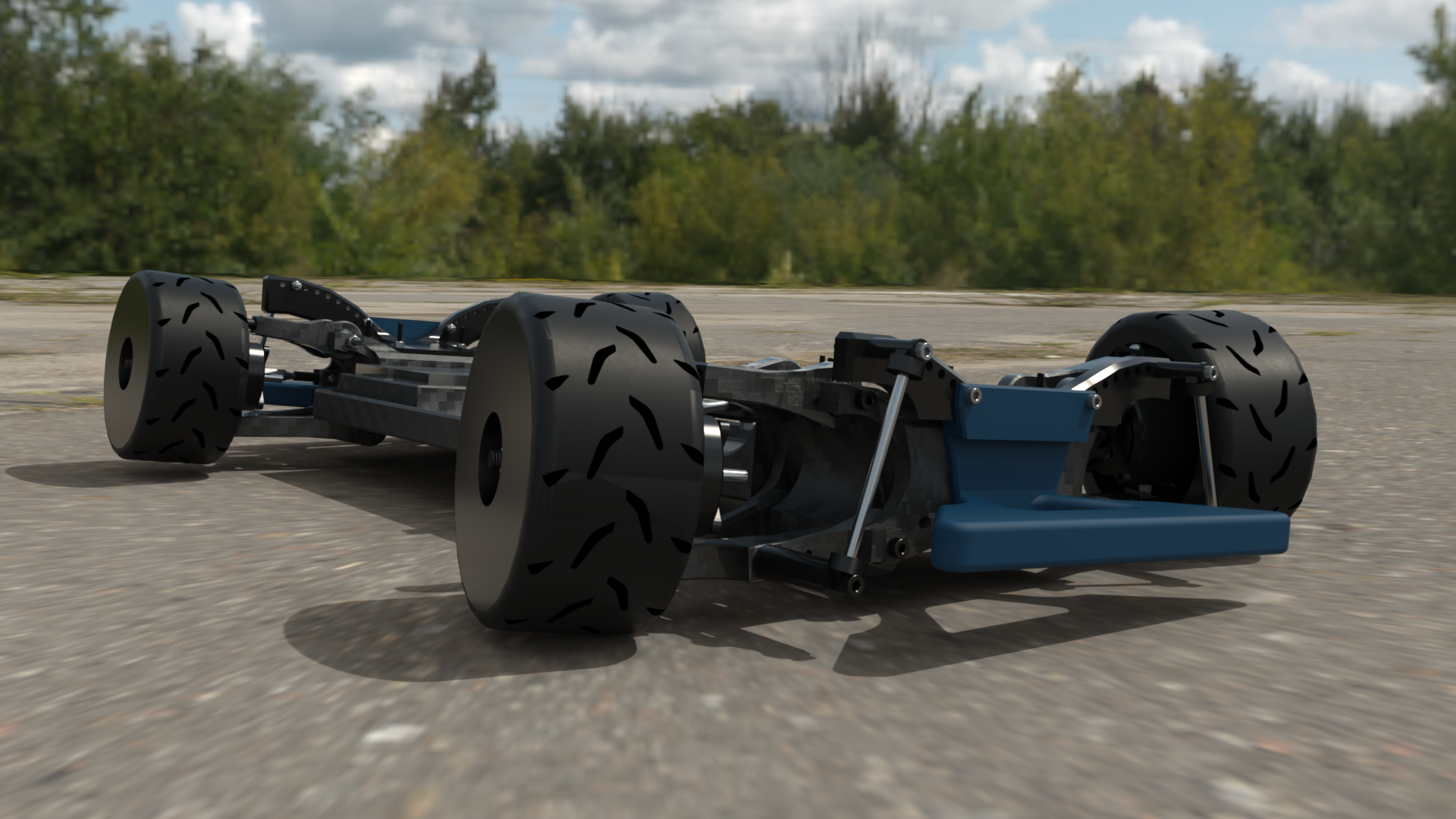
A 1/7 scale electric RC car with four independent hub motors, ESP32 control, wheel-speed feedback, an inertial sensor, and custom suspension and steering systems.
Rendered view of the chassis and four-motor layout.
01 / Project overview
This educational project documents the mechanical, electrical, and embedded-control systems of a 1/7 scale RC car. Each wheel uses a separate brushless hub motor and ESC. An ESP32 processes radio inputs and sensor feedback, then commands the drivetrain and steering.
Driving video
Camera footage from inside the car shows the four-motor system in action during a driving test.
public/videos/car-pov.mp4.
The radio sends throttle, steering, shutdown, and driving-mode requests to the car.
The ESP32 interprets those requests and decides how the steering and four drive motors should respond.
Each wheel can receive its own power command while the steering servo follows the driver's requested direction.
Wheel-speed and motion sensors show how the car actually responds, allowing the controller to correct its path.
02 / CAD assemblies
The viewer contains the full vehicle assembly and an exploded wheel view. The status label identifies an imported model, captured drawing, or generated reference model.
03 / Mechanical motion
The CAD animations show the steering-linkage range and the suspension travel around the hub-motor assembly.
M01 / Steering sweep
The top view shows the two uprights moving through their steering range while the rack and tie rods maintain coordinated wheel angles.
M02 / Suspension cycle
The suspension study cycles one corner through vertical travel and shows the upright and control-arm motion around the hub-motor package.
04 / Vehicle control
The ESP32 reads the radio receiver, wheel-speed sensors, and inertial sensor. It sends independent commands to four ESC channels and one steering servo.
The controller continuously reads throttle, steering, and mode requests from the radio system.
Forward, reverse, and steering requests are converted into PWM commands for the four ESCs and steering servo.
The controller compares requested motion with measured wheel speed and yaw, then adjusts left-versus-right power when assistance is enabled.
These limits reduce abrupt commands and define the controller's failure behavior.
05 / Feedback control
An interactive explanation of the firmware controller: yaw uses proportional-integral feedback, wheel-speed difference uses proportional feedback, and total requested power is preserved.
correction = Kpyaw x yaw error + Kiyaw x accumulated yaw error + Kprpm x RPM-delta error
Yaw KpResponds immediately to the difference between requested and measured yaw rate.
Yaw KiBuilds correction when a smaller persistent tracking error remains over time.
RPM KpCorrects left-versus-right wheel-speed mismatch without storing error history.
Full assist active
One-step visualization. The firmware also carries a bounded yaw integral through time.
06 / Hardware stack
Each wheel has a separate motor and ESC. The ESP32 receives driver input, four wheel-speed signals, and chassis acceleration and rotation data.
DOIT DevKit V1 running ESP-IDF 6.x.
550KV, 12N14P brushless hub drives.
Separate throttle and reverse signal inputs.
Driver control, shutdown, and selectable driving modes.
208 Hz accelerometer and gyroscope configuration.
Individual motor-speed measurement at every wheel.
07 / Specifications and results
Measured and planned vehicle performance values. Each completed result includes its units and a short description.
Values without a completed test are labeled Not tested.
08 / Firmware
The firmware is divided into modules for radio input, steering, motor control, sensors, torque vectoring, calibration, and monitoring. Each module has a separate hardware or control responsibility.
09 / Project progress
The control firmware is operational. Current work covers sensor validation, repeatable full-car tests, and calibration of the torque-vectoring controller.